Race Car Chassis Design
 There are 10 key factors to be considered when designing a suspension system, whether it’s for a single seater or sports prototype, and part of the skill of the designer lies in reconciling the conflicts between them.
Of course, one aims to avoid compromise in any direction, but inevitably some criteria will be given priority over others. The most important of these are:
- Installation stiffness
- Car packaging (aerodynamics, chassis structure and regulation requirements)
- Cg height
- Unsprung weight
- Cooling (brakes and bearings).
Other, secondary, priorities include – in no particular order:
- Cost
- Ergonomics
- Design resources
- Motion ratio
- Geometry
Other designers will perhaps have different views on these priorities.
But while mechanics and bean-counters may not like it, I feel that non-performance-related factors such as ergonomics and cost must be secondary on a vehicle for which performance is the prime objective. More surprising to some will be the secondary priority I give to geometry, and I discuss that later, but I should emphasise that if Priority one equals 100, then Priority two equals 90: in other words, everything matters.
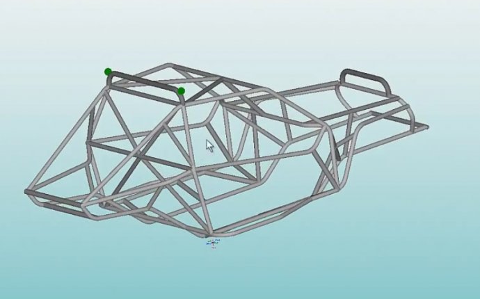
Prime priority among the 10 is car packaging, because unless the car complies with the regulations, it doesn’t race, and unless it works aerodynamically, it doesn’t win. Compared to a single seater, where the rotating tyres have a major and largely immutable influence, the enveloping bodywork of a prototype has much greater aerodynamic, and therefore performance, significance. Together, the regulations and the aero programme will define the volumes available for the front suspension, whereas the rear suspension will be controlled by the structure and the aerodynamics.
On my last design, the Lister Storm LMP – which is my reference throughout this article – I chose to take the cooling air for both radiators and front brakes through the front suspension. To minimise blockage from suspension members and to clear the front brake scoops, there was a large vertical separation between top and bottom wishbones, the top wishbone positioned as high as possible within the (18-inch diameter) wheel rim. That had other beneficial effects, such as reducing the loads in the wishbones, aligning the wishbone load paths with the top and bottom skins of the footwell (the minimum height is controlled by regulation), and allowing a reasonably vertical angle for the pullrod.
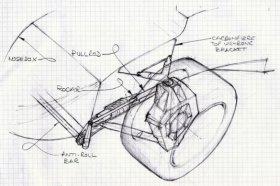
Pullrod actuation is unconventional in modern sportscar terms, but I chose it for a number of reasons. From a packaging point of view, it meant that I could fill a vacant volume with springs and dampers while keeping the bonnet line (usually raised to cover pushrod-operated dampers) very low. Also, it offered a lower Cg height than a pushrod installation and the ability to reduce weight and cost by using one suspension bracket to perform multiple functions: our ‘multi-bracket’ (and its dedicated chassis insert) provided mountings for the front leg of the FLWB (front lower wishbone), the damper unit, the anti-roll bar and the nosebox. The double-shear rocker pivot is also rather lighter than the usual single-shear pushrod type, and feeds its loads directly into the stiff intersection of footwell side and floor. The pullrod is steep and short, and can therefore be small in cross section. Obviously, the compressive loads seen by a pullrod are small, so that buckling is not a concern, and a small cross section is beneficial since the pullrod is in the cooling airflow.
The main trade-off was of course with ergonomics, where the pushrod arrangement is unbeatable. Also, I was rather constricted in the length of damper, and hence the motion ratio, I could use. For a Prototype, I would prefer around 0.8:1, with the damper moving 1.25 times the wheel displacement: the Lister has rather less than this on the front. I also traded off suspension link length for the reduction in bonnet height allowed by the use of pullrods. Since the footwell must be a minimum of around 690mm (27.2in) wide, in order to use a long lower wishbone in conjunction (for aerodynamic reasons) with a raised footwell, it is necessary for the FLWB rear leg either to pass through the footwell wall or below the footwell. Either of those options compromised the chassis structure too much, so I chose a short FLWB, the inboard mountings of which are bolted to the bottom corner of the footwell. That decision having been made, the FTWB length became easy to define.
My attitude to suspension geometry is pragmatic, and, in the absence of the requisite tools, fairly untrammelled by science. It’s not that I believe suspension geometry is irrelevant – far from it, I think it’s very important – but design is about best use of available resources, whether money, time, material, manufacturing techniques or engineering analysis tools. For example: roll centres are in actuality force-dependent, not geometry-dependent, and therefore require more sophisticated analysis tools than were available to me.


